This is the second part of the posts covering the Rove canal tunnel. In the first part the canal was approved and construction given the go ahead. The canal and the tunnel’s construction finally began in 1905(**).
Due in part to the massive Rove tunnel, it was predicted that the Marseille-Rhône canal would take eight to ten years to build. Work started in 1910–11. Although World War I created some setbacks, jail labour was used to help move things ahead, and eventually, a lot of labour was transferred from Italy and Spain to keep the building process moving.
Certain sections of the new Marseille-Rhône canal were actually begun in 1905, more than five years before the tunnel itself was commenced. This entailed among other things, the enlargement of the La Lave basins and new jetty facilities in the Etang de Berre. **In addition to that work also began in that year began on the first of the three shafts needed for the tunnel (see the note below).
**NOTE: It has often been implied that work began on the tunnel in 1906. The discovery of a report in La Croix des Marins (The Sailors’ Cross) newspaper for 17th December 1905 however reveals that work on the tunnel had begun starting with the shaft at Logis Neuf. This would be the first of three important shafts needed for construction. The depth at Logis Neuf would be 120 metres, and by starting here first, the work would enable a study of the geological conditions deep below the Nerthe mountains to be undertaken. By the time the main tunnel construction began, Logis Neuf became the second of three shafts to be enabled along the line of construction. There are in fact five shafts these days however two additional ones were built in the 1960s as part of substantial work following the tunnel’s failure that year.
The main body of canal and tunnel were begun in 1911. It was dug using a series of galleries that were later expanded. The following illustration gives an idea of that.
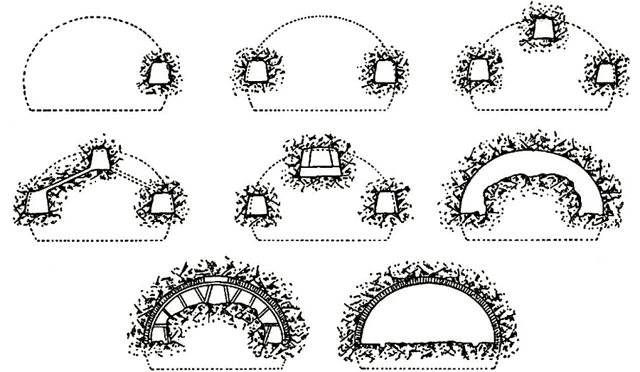
The methodology involved in excavating the Rove tunnel. Slide Player.
Pretty much of the tunnel was dug in a direction from the south to the north. Some tunnelling work was done from the north however most of the work in the Marignane area was focussed on the deep cuttings required to take the canal towards the inland sea known as the Etang de Berre. The main drive from south to north was because most of the facilities, including those for maintaining the locomotives, trucks and equipment, was in the south.
The modus was to drive a main header towards each of the three shafts that had been built, and once that was completed to expand outward and downward with further galleries. The shafts were important because these would double as pumping stations for the water that was expected to be found. The shafts at Sainte Maxime and Vallon were secondary shafts, with the main one (some way short of the half way mark) at Logis Neuf. This shaft still exists for ventilation. Had that shaft indeed been built half way it would have been an impressionably deep one, but by siting it in a depression within the mountain range, its depth was a more manageable 140 metres (459 feet).
For instance, in July 1913, the advance galleries were constructed as follows (from the southern end). That at the top of the arch had dug 1,800 meters. The south west side header (left hand side) had reached two kilometers. On the right the length had reached 2,150 meters. Because the shafts that were built had been excavated just off the tunnel’s northeast side (and which would be linked to the tunnel via an adjoining passage) this header was being pushed the most.
It’s interesting to note when two further shafts were sunk in the 1960s, the same modus was used – these were sunk on the north east side of the alignment with connecting passages into the main tunnel. For the tunnels’ contractors, the sooner the works reached the Logis Neuf shaft at 2.500m, the more convenient this would be because ventilation was being provided by way of a 50hp fan that sent air to various parts of the bore via a 50cm diameter pipe. Even so the air quality dropped the further the tunnel went thus the need for a new source of fresh air was pressing.
Lighting was provided by acetylene lamps because the nature of laying electricity cables in an often fluid environment wasn’t seen as being safe. Electricity was provided only where the main tunnel had been completed.
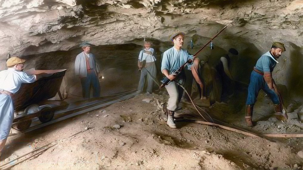
Besides the other gauges used in the tunnel’s construction, the rarer Decauville built 600mm gauge track and trucks were also used in some sections. Image upscaled and colourised by the author from an original small sample.
The final section between the south and northern headings (at 4.7km from the southern end) was dug out on 19th February 1916. Soon after that major celebrations were held to mark the occasion a full working tunnel had been dug between La Lave and Gignac. More of that later.
The railway was sustained by a series of maintenance workshops, and one of those even had a specialist role of building the numerous trucks needed for the spoil trains. On top of that there was an infirmary, dormitories, and baths and showers that were required by the workers.
The amount of spoil excavated for the Rove tunnel was far in excess of those dug for the world’s longest railway tunnels at the time. For example the famous tunnels through the Swiss alps had far less spoil removed than that at Rove. The Lötschberg had 1,000,000 cubic yards of spoil excavated, the Gothard 1,800,000 cubic yards and the Simplon 2,100,000 cubic yards. At Rove a total of approximately 3,000,000 cubic yards was excavated – although it seems some of that total takes into account the deep Gignac cutting.
The tunnel construction railway system
The primary excavation started in 1911 with a main header at the upper portion of the site where the arch would eventually be constructed, as well as two pilot tunnels about where the twin towpaths would eventually be. A contractor’s railway was utilised to transport the spoil out of these. The main railway system and tunnel machinery were positioned in a massive cavern that was soon created after numerous galleries were driven across and additional headings were formed. The main tunnel bore was then largely excavated.
The canal tunnel was built using an extensive railway network. A 760mm gauge system was utilised for the more complex parts of the tunnel’s construction, such as the headers where the workfaces were situated, while a standard gauge system was used for the heavier tasks, such as removing large amounts of spoil. The narrow gauge rails were used in the part on the right (or the north east side) where the majority of the excavation was to occur, while the standard gauge was often located to the left side of the works heading north.
A 600 mm gauge system were also used for part of the work. The 600mm gauge is clearly described in some accounts of the tunnel work and its known the track and the trucks came from Decauville. It may have been a cheap off the peg purchase. Decauville 600mm was one of the company’s least successful products, thus it might have been what could be described as end of stock. The 600mm gauge was used from the north to some of the advance tunnels that were being driven – thus it might have been an attempt at speeding up the transfer of spoil away from the works.
Curiously the northern part of the works employed three gauges – standard gauge, 750mm gauge and 600mm gauge. The combined 600mm and 750mm gauges in fact constituted standard gauge, thus what happened was the standard gauge system was laid down through the northern section of the tunnel works with an additional rail slightly off centre to form the two narrow gauge lines. The following picture shows this arrangement clearly.
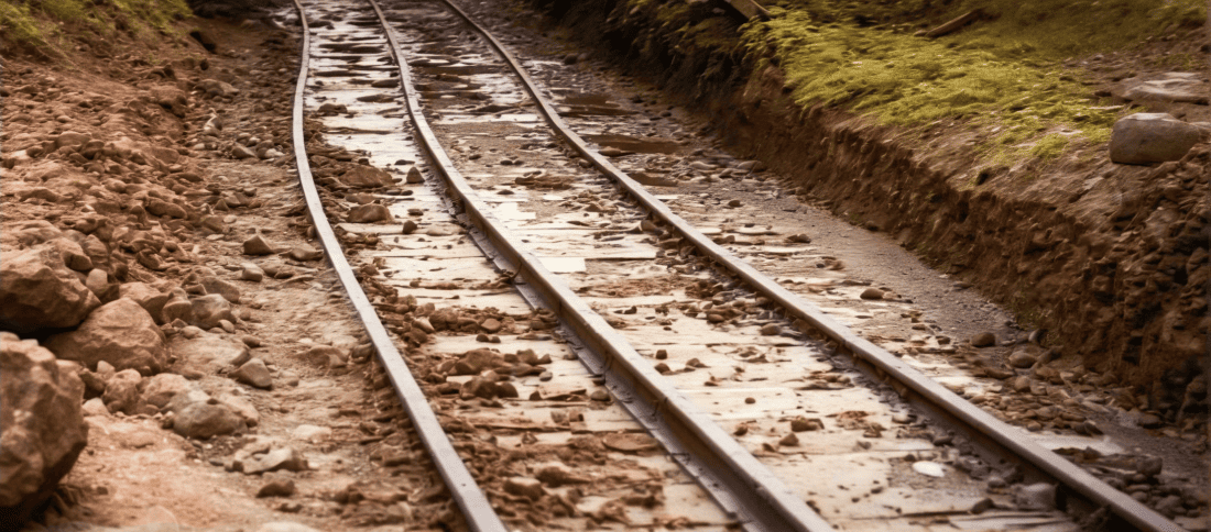
The three railway gauges in use at the northern end of the Rove tunnel construction. At left is the 600mm gauge. On the right is the 750mm gauge. The outer rails are 1435mm. Th difference however is 1350mm – and that is made up by the width of the centre rail at approximately 85mm to incorporate the two narrow gauges into the standard gauge trackage. This image is adapted from a crop of one found at Gallica and colourised by the author.
Leave a Reply