The ingenious arrangement meant the construction trains (and indeed the tunnel’s passenger trains) at all three gauges could be hauled by either the 750mm gauge compressed air locomotives or the standard gauge locomotives. No 600mm gauge locomotives apparently were used because those tracks were largely used in constricted spaces (such as the headers) and were pushed or hauled by the workers.
Again, the nature of construction, including the use of railways, meant just three shafts were required. These were deliberately kept to a minimum because of the great height of the hills above its course – rising to perhaps around a thousand feet. The more central one being at Logis Neuf and now a ventilation shaft – with the others at Vallon (the southernmost) and Sainte Maxime (the northernmost).
As seen in the above diagram, a number of galleries are created and headers are driven in place of shafts. And in parts this was where the 600mm gauge track came into use. The excavated material was removed with the use of hand-propelled small wagons and rudimentary tracks supplied by Decauville. The way the system operated was that the upper galleries were excavated, and the spoil was transported to shafts at regular intervals using crude tracks. Compressed air locomotives in the lower levels would then marshal the spoil to distribution points so that the tunnel’s steam locomotives could haul it out after it had been dropped down the shafts and into narrow gauge trucks. of the 750 mm gauge. The totality of the railway in the tunnel was around 30 km at its greatest extent.
The only problem with this method was the rapidity of the upper galleries’ excavation was more than challenging for the railway that took the material out. In addition to pauses brought on by water intrusion, the rate at which spoil material was removed also hindered digging. Not because it was a faulty arrangement, but rather because the rate of tunnel excavation could not be adequately met by the spoil disposal capability. This became less of an issue as the tunnel was expanded and more tracks were used.
Once the galleries had been sufficiently expanded and merged, the standard gauge railway in turn took over from the 750mm gauge to take out the ever increasing quantities of spoil. There’s a good picture illustrating how one of those galleries looked (even though the image is actually of the section of tunnel leading into the works at the north portal) and complete with timber supports and narrow gauge railway lines. This example clearly shows the three different railway gauges in use within the tunnel works.
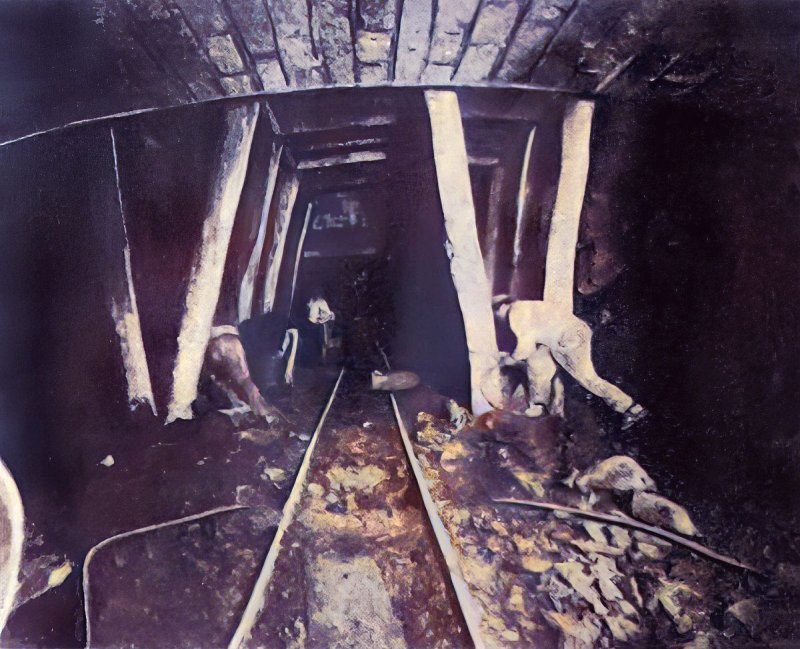
One of the tunnel’s headings, with a section of the arch already built c1921. The narrow gauge railway used in this specialist work is evident. Small image sourced from Internet Archive and upscaled/colourised by the author.
As construction went on to expand the tunnel’s bore, the narrow gauge was being used in the deeper trenches whilst the standard gauge was usually at an intermediary or upper level which was more in line with the ground levels at surface. The arrangement meant larger quantities could be conveyed out of the tunnel and any gradients the standard gauge locomotives might face were reduced to a minimum so that the longest and heaviest trains could be hauled without much ado.
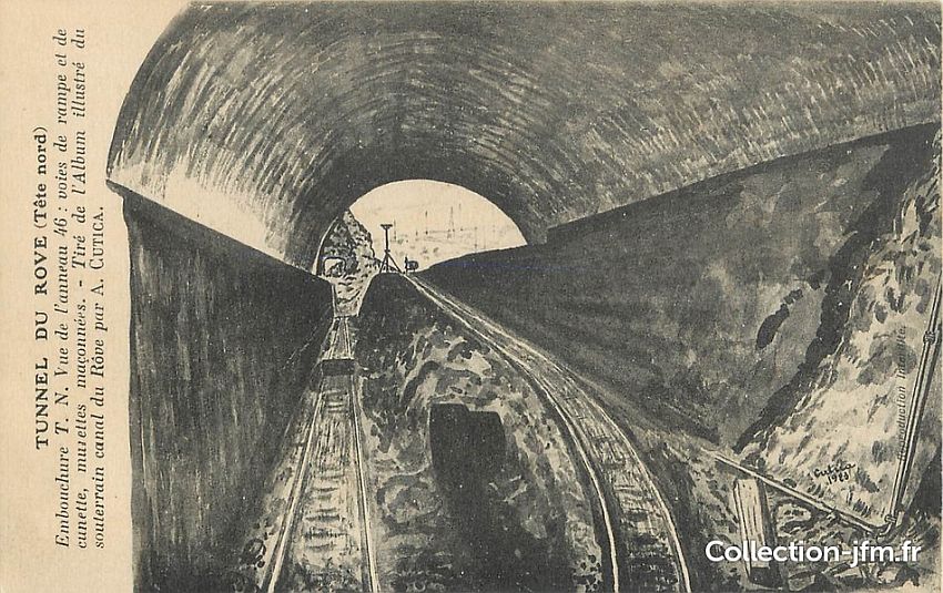
This drawing shows the different levels of railway at the Marignane (north) portal The 750mm gauge lines are in the lower trenches whilst the standard gauge is just out of sight at the upper level. By this time it seems the 600mm gauge system had been dispensed. More views in the second instalment of this feature. Collection JM FR.
The majority of the work deep inside the construction was completed by compressed air locomotives, which also handled shunting, collecting, and distributing newly empty trucks to the working faces. They could work with up to 25 trucks loaded. After being transported to collection sidings, these trains were reassembled into longer trains with as many as 70 trucks. The steam locomotives would pull these out of the tunnel.
Compressed air was delivered inside the tunnel by means of piping to loading stations sited every 550 yards, from which the locomotives were able to top up their tanks. The railway locomotives and trucks were maintained in a huge depot that contained 250 workers, whose job it was to also maintain the other equipment and machinery required in the tunnel’s construction.
The compressed air locomotives were built by two companies. One was Porter’s of Pittsburgh, who had 90% of the world’s market for these types of locomotive. the other was a French company who followed a design drawn up by the tunnel’s engineer Mr. Léon Chagnaud – noted for a number of projects – including construction of Paris Metro line 4 and the Lötschberg Tunnel. Metro line 4 was the first of a very small number of Paris Metro lines that pass under the Seine rather than over it.
There were seven of these compressed air locomotives at work in the tunnel. Complementing these were also five steam locomotives. From time to time, depending on conditions and the location of the three shafts concerned, these would be allowed to work quite a distance into the tunnel. Indeed during 1922 the steam locomotives from the southern end of the works reached a distance of 5km into the tunnel.
Steam traction also operated for the Gignac cutting work. These locomotives were significantly larger and these almost never ventured into the actual tunnel works. To show the work being done in and around the tunnel’s north portal, and towards the southern end, a special train made up of French government ministers and their entourage, including journalists, was employed in 1916 – and this train employed a standard gauge tank locomotive hauling a passenger train of 750mm gauge.
Two enormous excavators bought from the Panama Canal were employed at the cutting on the northern approach. Unfortunately, due in part to the start of hostilities, spare parts for the machines had become impossible to obtain, therefore these were soon put out of service. This was another area of work that was hindered by hiccups in progress.
Continued in part three.
Leave a Reply